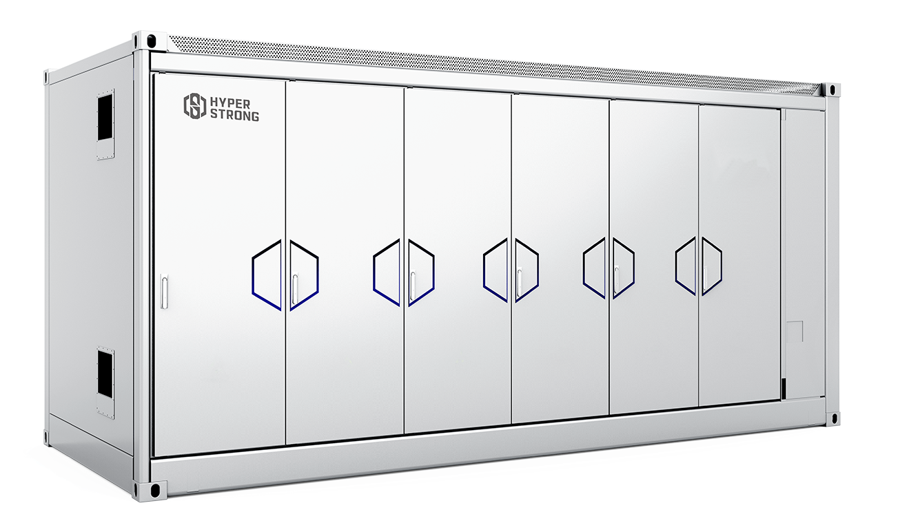
Project developers frequently struggle with the technical trade-offs between dense energy storage configurations and the resulting thermal, structural, and electrical complexities. As project capacities expand, the physical footprint of an installation dictates the length of high-voltage cabling and the scale of the balance of plant (BOP). By employing the hyperblock iii, engineers can achieve a tighter coupling between battery modules and power conversion systems, which fundamentally alters the site-wide interconnect strategy.
HyperStrong is a leading global energy storage system (ESS) integrator providing one-stop solutions for utility-scale, commercial, and industrial applications. Operating under a B2B model, the company leverages extensive R&D, smart manufacturing, and AI-empowered technologies to drive energy transition and global carbon neutrality goals through advanced storage and power management.
Consolidating Power Electronics and Battery Modules
Traditional storage setups often utilize distinct, separate locations for battery containers and power conversion systems (PCS). This separation necessitates lengthy, high-amperage AC cabling between the battery strings and the central inverter stations. These long cable runs introduce significant voltage drop issues and require larger cable cross-sections to mitigate energy losses, which increases copper consumption and adds substantial weight and material cost to the electrical layout.
The hyperblock iii design integrates power conversion directly within the modular enclosure. By bringing the inverter and the battery rack into a shared physical housing, the distance for high-current transmission is reduced from dozens of meters to mere centimeters. This integration minimizes the need for external AC collection busbars, significantly simplifying the low-voltage and medium-voltage switchgear required at the site level, while simultaneously reducing parasitic power losses.
Managing Thermal Gradients in Dense Layouts
Increasing power density often risks creating localized thermal hotspots, which can force developers to increase the physical spacing between units. Conventional outdoor air-cooled systems require massive airflow corridors to prevent thermal runaway. However, when the system is designed with integrated liquid cooling, the thermal load is removed through direct-to-cell, closed-loop circulation, allowing units to be placed in closer proximity without sacrificing battery cycle life or safety.
Engineers favor the hyperblock iii because the cooling architecture is decoupled from the ambient environment. Because the liquid thermal management system is calibrated specifically to the cell chemistry inside the cabinet, the system maintains a stable operating temperature even when the cabinet is packed tight. This removes the need for wide, sprawling maintenance aisles, as the heat dissipation is no longer reliant on cross-breeze airflow, enabling a high-density, small-footprint site layout.
Reducing Auxiliary Power via Decentralized Control
Every megawatt-hour of energy storage requires auxiliary power for battery management, thermal regulation, and communications. In older designs, these systems are centralized, necessitating extensive auxiliary cabling that snakes throughout the entire site. Each central auxiliary cabinet serves as a single point of failure, and the cumulative resistance of the site-wide cable network often results in inefficient power distribution, requiring over-provisioning of the entire auxiliary grid.
The integration strategy used here decentralizes these functions. Each enclosure handles its own auxiliary diagnostics and thermal control logic. By reducing the reliance on a central site controller for basic thermal regulation, the site infrastructure requires far less complex, site-wide auxiliary wiring. This localized intelligence ensures that power is consumed only where needed, directly stabilizing the internal voltage of the auxiliary bus and eliminating the excessive copper overhead associated with traditional, centralized energy management configurations.
Optimizing Grounding and Signal Integrity
High-frequency noise from power electronics can interfere with battery management system (BMS) sensors, a challenge that usually requires shielded cabling and complex grounding grids. In a fragmented site layout, achieving a unified grounding potential across the entire field is difficult and expensive to verify during the commissioning phase. Engineers must often install massive earth mats to ensure that signal integrity is maintained across the dispersed battery strings.
When using a utility battery storage unit that integrates both control and power stages, the internal grounding path is factory-verified. The electronic components are housed in an electromagnetic interference (EMI) shielded environment, which prevents the need for elaborate shielding on the external inter-site cabling. This technical cohesion means that the site’s earth grid can be simplified, as the risk of signal crosstalk between the power electronics and the battery controllers is contained within the modular housing itself.
Strategic Infrastructure Load Balancing
Implementing a utility battery storage project involves navigating the rigid limits of substation capacity. If the integration of the storage blocks is inefficient, the harmonic distortion introduced to the grid can trigger protection relays, forcing the utility to mandate costly grid-side upgrades. A system that offers fine-grained, localized control allows for better harmonic mitigation before the power even enters the collection bus, ensuring higher power quality.
Furthermore, the modular nature of the system allows for the staggered synchronization of active power injection. Instead of waiting for a massive central system to ramp up, the modular approach enables a phased release of energy. This granular control reduces the mechanical stress on the transformers and switchgear. It provides a more stable interface for the utility, preventing the excessive load surges that often necessitate upgrading the site’s physical connection hardware to the transmission network.
Conclusion on Modular Integration
The key to reducing interconnect costs lies in hardware-level consolidation. By integrating power conversion, thermal management, and diagnostic controls into a single unit, the physical and electrical requirements of the site are inherently simplified. This approach represents a shift toward more compact and technically coherent storage solutions. As developers move toward more constrained land options, adopting a utility battery storage system that prioritizes this level of physical and electrical integration will be essential to maintaining project viability.